
Edible Oil Refineries
In a refinery, most of the piping is cut, welded and erected at site. What reaches the fabricator decides how fast — and how well — it goes up.
Degumming, neutralising, bleaching and deodorising sections are dense with vessels, heat exchangers, steam and thermic-fluid lines and vacuum systems, stacked over several floors of structure. The site team builds from drawings and from what they can picture. We give them both: printable drawings a fitter can work from, and a model they can walk through before a pipe is cut.
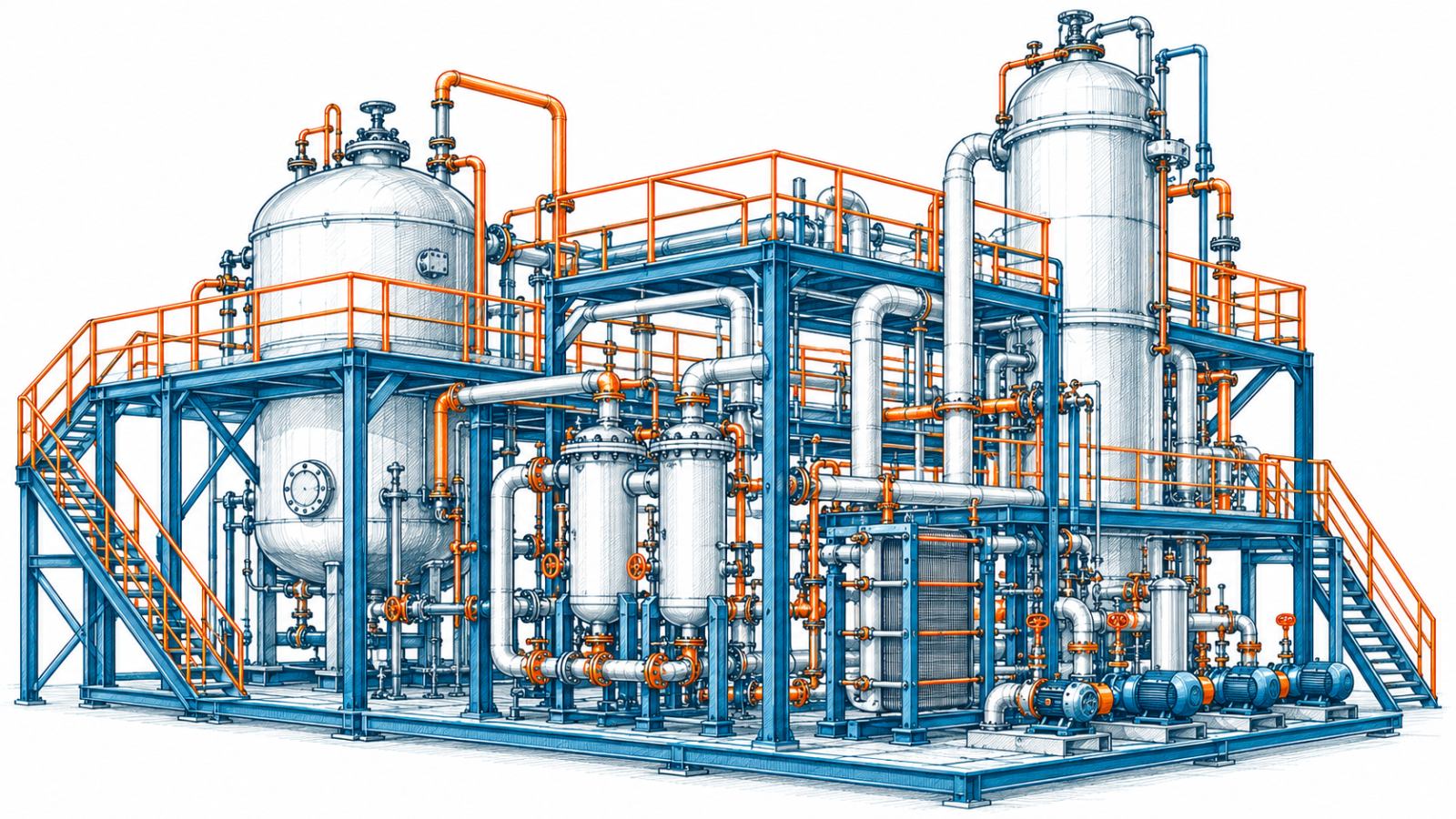
Engineering for Edible Oil Refineries
-
01
Drawings made for the fabrication yard
Isometrics carry dimensions, elevations, fittings and the material list on the sheet itself, so a fitter can cut and weld from a printout without calling the office. GA drawings are split by floor and area, at scales that stay readable on paper.
-
02
A model the site can walk through
Some arrangements are easier to understand in 3D than on any drawing. A navigable model of equipment, structure and every routed line lets the site engineer check a route, an elevation or a valve position on a laptop — before work starts, not after.
-
03
Hot lines, cold lines, insulated lines
Steam, condensate and thermic-fluid lines run alongside product lines that must not lose heat. Routing allows for insulation thickness, expansion and drainage, so lines can be insulated, traced and maintained once they are in.
-
04
Refineries grow in stages
A new section, a capacity increase, a unit added a few years on. Layouts keep room on the structure and racks for what comes next, and an up-to-date model makes the next tie-in far easier to plan.
Systems, deliverables and related services
Systems we work on
- Degumming and neutralisation
- Bleaching and filtration
- Deodorisation
- Steam, condensate and thermic fluid
- Vacuum systems
- Tank farm and transfer piping
- Utility piping
What you receive
- Floor-wise piping GA drawings
- Fabrication-ready isometrics with material lists
- Support drawings
- 3D model files for site walkthroughs
- Piping and support MTO
Related services
- Piping Design & Engineering Piping routed from P&ID to a layout that can be supported, operated and built.
- 3D Plant Modeling & Coordination One coordinated model of equipment, piping and structure, reviewed for clashes before drawings are issued.
- Drawings & Documentation Issue-ready drawings and material take-off, checked before they leave the office.
Tell us about your project
Send us your P&ID, GA or scope and we will come back with how we would approach it.